How Can We Help?
-
Controllers
-
- Pro-160 / 360 Fault Codes
- Pro-160 / 360 Temperature Sensors
- Pro-100 / 160 / 360 to Hall Throttle Wiring
- JSK-120 Driving Two Pro-360s
- RBT and Pro-160 / 360 P3 Pot Fault
- Pro-160 / 360 Dual Control
- Pro-100 / 160 / 360 Radio Control Failsafe
- Pro-100 / 160 / 360 to JSK-100 wiring
- Pro-100 / 160 / 360 Failsafe Contactor
- Double Heading the Pro-100 / 160 / 360
- Pro-160 Layout Diagrams
- Pro-100 / 160 / 360 Software Versions
- Use with shunt wound motors
- Use with Series Wound Motors
- Updating Firmware
- Double Heading Pro-160 / 360 & 4QD Series
- Push Button Mode With Limit Switches.
- Pro-100 / 160 / 360 Troubleshooting
- Speed Sensor Ratio
- Push Button - Forward / Off / Reverse Operation
- Show Remaining Articles (5) Collapse Articles
-
- Pro-160 / 360 Fault Codes
- Pro-160 / 360 Temperature Sensors
- Pro-360 Heatsink Removal and Replacement
- Pro-100 / 160 / 360 to Hall Throttle Wiring
- JSK-120 Driving Two Pro-360s
- RBT and Pro-160 / 360 P3 Pot Fault
- Pro-160 / 360 Dual Control
- Pro-100 / 160 / 360 Radio Control Failsafe
- Pro-100 / 160 / 360 to JSK-100 wiring
- Pro-100 / 160 / 360 Failsafe Contactor
- Double Heading the Pro-100 / 160 / 360
- Pro-100 / 160 / 360 Software Versions
- Updating Firmware
- Use with shunt wound motors
- Use with Series Wound Motors
- Double Heading Pro-160 / 360 & 4QD Series
- Push Button Mode With Limit Switches.
- Pro-100 / 160 / 360 Troubleshooting
- Pro-360 Locknut Service Bulletin
- Speed Sensor Ratio
- Push Button - Forward / Off / Reverse Operation
- Show Remaining Articles (6) Collapse Articles
-
- Pro-100 Fault Codes
- Pro-100 / 160 / 360 to Hall Throttle Wiring
- RBT and Pro-160 / 360 P3 Pot Fault
- Pro-160 / 360 Dual Control
- Pro-100 / 160 / 360 Radio Control Failsafe
- Pro-100 / 160 / 360 to JSK-100 wiring
- Pro-100 / 160 / 360 Failsafe Contactor
- Double Heading the Pro-100 / 160 / 360
- Pro-100 / 160 / 360 Software Versions
- Updating Firmware
- Use with shunt wound motors
- Use with Series Wound Motors
- Pro-100 / 160 / 360 Troubleshooting
- Speed Sensor Ratio
- Push Button - Forward / Off / Reverse Operation
-
- Mosfet Insulator Arrangement DNO & Porter
- How To Wire Up a Porter 5
- Closed Loop Current Control
- Fitting a Porter to a PDQ Power trike
- Driving the Porter by Raspberry Pi
- Porter: Disabling Regenerative Braking
- Porter Current Limit Adjustment
- DMR-203 Radio Control of a Porter 5 / 10
- Porter 40 Speed Controller
- Porter 40: Use with PWM Input
- Porter Troubleshooting
-
-
- PRO-150 Overview
- Double Heading for the Pro-150 and 4QD Series
- Pro-150 Hall Throttle Supply
- Pro-150 Hall Throttle Programming
- Pro-150 Push Button Use
- Use with shunt wound motors
- Pro-150 Fault Finding Guide
- Pro-150 Pt Fault Code
- Pro-150 programmable parameters
- Pro-150 Mechanical Information
- Pro-150 Basic Wiring Diagram
- Fraser Golf Buggies, Wiring for Pro-150
- DMR-203: Use with PRO-150 Controllers
- Pro-150 Capacitor Modification
- PRO-150 Current Limit
- PRO-150 Issue History
- PRO-150 Joystick Programming
- Show Remaining Articles (2) Collapse Articles
-
- 4QD-200/300 Overview
- Double Heading for the Pro-150 and 4QD Series
- Control Board Jumper Positions
- Ampflow motor
- Damage From Blown Mosfets
- DMR-203: Use with 4QD Series Controllers
- Battery Contactor for 4QD-200 / 300
- Adjustment for 48V
- Inhibit switch / footbrake - 4QD series only [tour 16]
- Forward / Off / Reverse Mode (4QD Series)
- Converting Parking Brake to Brake Light
- Disabling HPLO on Early 4QD Models
- Inhibit Ramp Modification [4QD series]
- Over voltage protection in the 4QD series
- Deadband values and removal
- How to dismantle the 4QD series
- Fault finding on the 4QD series
- Testing the 4QD Base Board and MOSFETs
- Reverse Acceptance Threshold [RAT] Modification
- Current limit resistors
- Use with Tacho Feedback Board
- Control Board Modification [Pre June 2010]
- Reverse Speed Modification [pre issue 17]
- Reversing Latch Modification [pre issue 16]
- Damage from a Reversed Battery (4QD Series)
- Mixing 4QD 150 / 200 / 300 series boards
- 4QD version history
- Inhibit
- Show Remaining Articles (13) Collapse Articles
-
- Damage from Reversed Batteries (NCC/VTX)
- Waveforms and Fault Finding
- Ramp Timings (NCC)
- Internal Power Supply and Protection Circuitry
- Fitting Expansion Connector
- NCC Speed Controller
- VTX and NCC Operating Voltages
- NCC Circuit Description
- VTX / NCC Fault Finding
- NCC Mark 2 Issue Number History
- NCC Mark 1 Issue Number History
- NCC Key Components
- NCC Zener Diode Failure
-
- Internal Power Supply and Protection Circuitry
- Current Limiting in the Pro-120 [and others]
- Pro-120 Mk1 History
- Pro-120 Mk2 History
- Pro-120 Key Components
- Earth Fuses: Why Do They Blow?
- Modifying the Pro-120 for other voltages
- Pro-120 Fault Finding Tips
- PRO-120: Multiple Slaves
- PRO-120 Ramp Reduction
- Fitting Expansion Connector
- Pro-120 Modification to give Uni-Directional Control
- Pro-120 Robot Wars Version
- Pro-120 Ignition Options
- Battery Discharge Protection: PRO-120
- Pro 120 Mark 1 Speed Controller
- PRO 120 Mark 1 - Additional Diagrams
- Show Remaining Articles (2) Collapse Articles
-
-
-
Accessories
-
-
- Articles coming soon
-
- Articles coming soon
-
- Articles coming soon
-
- Articles coming soon
-
- Articles coming soon
-
- Articles coming soon
-
Application Notes
-
- Alternative Double Heading [MU] Solution
- Double Ended Tram Control
- Loco Wiring: Auto Reversing Lights
- Speed to RPM Calculator
- Noise Suppression for Multiple Motors
- DCC / Airwire Interface
- Phoenix Loco Wiring
- Loco Wiring: Hand Control & Horn Relay Board
- Double Heading Problems
- Motors in Parallel
- Basic Model Loco Installation [with RBT and HRB]
- Low Pulling Power
- Radio Control
-
-
-
Technical
-
- Speed to RPM Calculator
- Noise Suppression for Multiple Motors
- Improving Heat Dissipation
- A Basic Installation
- Motor Noise Suppression
- Catching diodes
- Multi speed control
- Parking Brakes in Series
- Fuses and Circuit Breakers
- Radio Control Wiring Hints
- Typical Wiring for the PRO-150, DNO, VTX and NCC Controllers
- Wiring for Hand Control and Radio Control
- Wiring for Push Button Use
- Good Wiring Practise
- Motors in Parallel
- Push Button Mode With Limit Switches.
- Forward / off / reverse mode or push-button operation
- Basic Model Loco Installation [with RBT and HRB]
- Pro-100 / 160 / 360 to Hall Throttle Wiring
- How do I select the parts?
- Use With Switch Mode Power Supplies
- Push Button - Forward / Off / Reverse Operation
- Wiring for Curtis ET-126MCU
- Radio Control
- DIN Socket Wiring
- Show Remaining Articles (10) Collapse Articles
-
- Current limit
- PCB numbers
- Acceleration and Deceleration Ramps
- Thermal shutdown
- Ignition
- Power down state
- Ramps
- Reversing
- Overvoltage protection
- Battery Discharge Protection
- Joystick [aka wig-wag]
- Parking brake driver
- Pot Fault Detection
- High Pot Lockout HPLO
- Reverse polarity protection [tour 26]
- Main Capacitor
- Radio control interface
- Tacho Generator Feedback
- Voltage Following
- What Does a Motor Speed Controller Do?
- Ignition Circuit
- Coulomb Counting
- Show Remaining Articles (7) Collapse Articles
-
- Using a BMS with a Motor Controller
- Mosfet Alternatives
- Testing an Electric Motor
- What is EMC [Electromagnetic Compatibility]?
- Closed Loop Current Control
- Battery Current and Motor Current
- MOSFETs
- Half bridge
- Switching frequency
- What is Regenerative Braking?
- Batteries
- Customised Arc Potentiometers
- What is PWM Motor Control
- Full Bridge
- Towing
- Torque
- Surge Currents
- Speed Stability
- Quadrants
- Heat
- Thermal shutdown
- Heatsinking
- Choosing a Controller
- Earth Track Fuse and Earth Loops
- Tacho Set-Up
- Charging a 24V Battery From a 12V Source
- What Voltage Should I Use? [12, 24, 36, or 48V]
- Positional Servo Control [DNO / VTX]
- POT Dead Band
- Why Do Mosfets Fail?
- Back EMF & Internal Resistance
- Use of Generators with Speed Controllers
- Control by Microprocessor
- Foot Pedal Idea
- Coulomb Counting
- Low Pulling Power
- Curtis Equivalents
- Show Remaining Articles (22) Collapse Articles
-
DNO Troubleshooting
This is the troubleshooting guide for the DNO range of controllers.
The DNO is the end result of a long line of 4QD analogue controllers including the NCC and VTXs. It is a well proven and reliable circuit and many thousands have been in use for many years. This page is to help identify and solve any problems that may occur.
The most common problem with the DNO is blown fuse tracks. These are weak points designed into the circuit board and are intended to protect the DNO from short circuits occurring in the associated control wiring. Their location is described in the manual and also shown below….
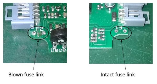
Blown fuse tracks display a burnt, copper colour. They can be checked with a multimeter on the resistance scale, and they are easy to repair by soldering a single thin strand of wire across the pads [Pro tip – fit a 0.9A self-resetting fuse to protect against further failures.].
Moving beyond the fuse tracks, there is a fault-finding sheet here which lists a number of key voltages to measure. We recommend printing this off and recording the voltages listed as this often gives a good indication of where problems are. There is a video here which shows how to do this.
If you do need to call us, please have this sheet completed beforehand, as it will give us at least some clue as to what is going on.
Other issues that we know about are…..
1. Tripping out due to condensation. The DNO has a current limit trip circuit, when the current exceeds a set limit for 17 seconds the controller will switch off and require an off / on reset to restart operation. The current trip circuit uses a pair of transistors in a high gain configuration to perform the trip operation, and this circuit can be susceptible to moisture or condensation on the circuit board. When this occurs the DNO will run for a short period but then stop responding to the throttle, and will need a power reset to restore operation. The problem occurs when the DNO is subjected to a sudden temperature change with high humidity levels. It can be cured by applying conformal coating to the components outlined in red below. RS supply 15ml bottles [part number 321-7324]. This was included in production from March 2021. In Dec 2023 we changed the gain of the transistors to make the circuit less susceptible.

2. Tripping out at high temperature. The current limit trip circuit can also give a false positive operation if the PCB is allowed to reach high temperatures. In tests the PCB has to reach over 50’C for this to occur, for this to happen the heatsink and mosfets will need to be over 80’C. If this problem is encountered, improving the cooling of the DNO will restore correct operation. This page gives more details on improving heat dissipation.
We came across this problem recently with a Toylander scale Landrover, after about 30 minutes running under heavy load the DNO started tripping out. We used a thermal imaging camera to examine the inside of the motor / controller compartment, this showed that the inside of the motors were reaching over 75’C, the hot air was then circulating and slowly overheating the DNO causing it to trip. The solution in this case was to fit a 24V, 80mm fan over one of the vents inside the motor compartment and wire it up to the ignition switch, this will extract the hot air whenever the Toylander is running.
3. Tripping out due to wrong connection. We have seen a few cases where the B+ wire has been accidentally connected to the adjacent M- terminal. When this is done, although the DNO appears to run correctly, the main capacitors rapidly overheat and cause the high temperature tripping described in 2 above.
4. Not switching from forward to reverse [or vice versa], this can occur if the acceleration and deceleration adjustments are set to their minimum values. There is a small interaction between these circuits and the dual ramp reversing circuit which can prevent the reversing circuit from activating. Increasing the ramp time slightly will cure the issue. In any case, having the deceleration ramp set to minimum is not a good idea as it can cause arcing at the relay contacts.